Ide Controller Diagram
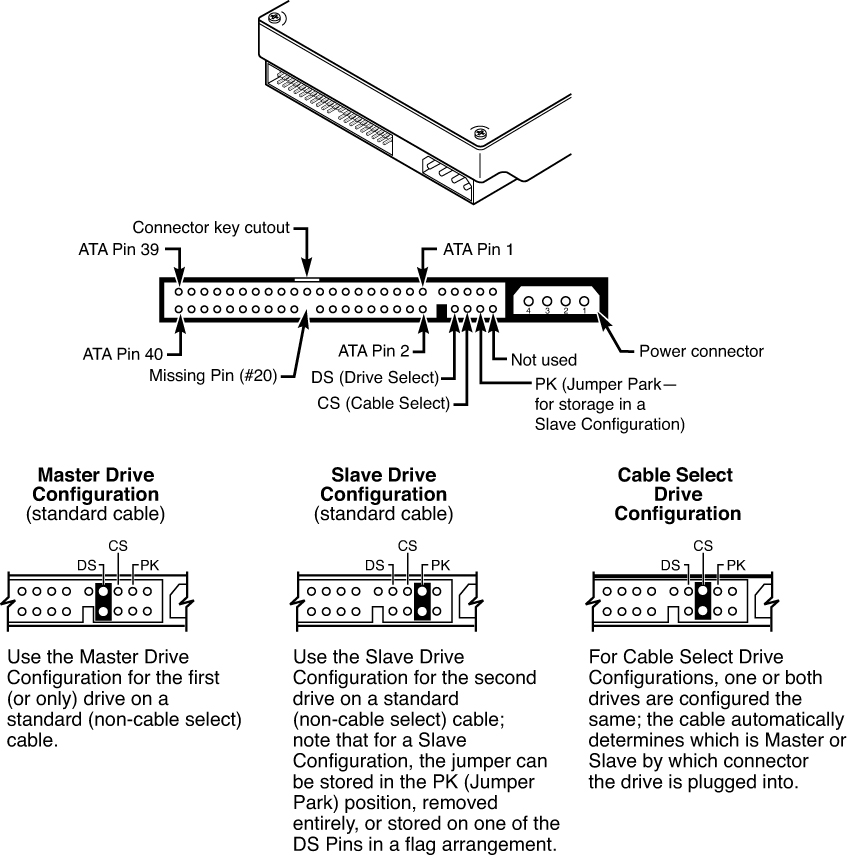
Only remember that one should be jumpered as master and the other as slave. Others such as sharpdevelop and lazarus do not.
 Ats Panel Genset Controller In Relay Panel Wiring Diagram Teknik Listrik Listrik Teknik
Making the connections with point to point wiring is relatively easy.
Ide controller diagram. How connect usb drive internal sata port ehow usb universal serial bus drives are becoming more and more common as people fill their computer system drives up with downloads of movies pictures and files. Computer aided control system microcontroller plc programmable logic controller pengenalan plc ladder diagram sistem kontrol pid sederhana scada supervisory control and data acquisition dcs decentralized control system. Most controllers also include some memory that acts as a buffer to enhance hard drive performance.
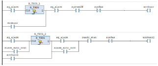
The ide ata interface consists of three blocks the cpu interface block that receives commands from the cpu the pio controller block that contains the pio state machine and the ide interface block that generates the signals required by the ide device to carry out data transfer with the host computer. The controllers are a mix of p and pid controllers. The diagrams use the standard px4 notation and each have an annotated legend.
Before ide controllers and hard drives were separate and often proprietary. This is a standard cascaded control architecture. Eide as of this article s printing the enhanced ide eide is the standard for ide drives.
An integrated development environment ide is a software application that provides comprehensive facilities to computer programmers for software development an ide normally consists of at least a source code editor build automation tools and a debugger some ides such as netbeans and eclipse contain the necessary compiler interpreter or both. All pins straight from 1 to 1 2 to 2 and so on. Figure 4 shows the wiring i used.
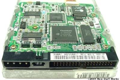
The controller is a small circuit board with chips that provide guidance as to exactly how the hard drive stores and accesses data. Estimates come from ekf2. If only one drive is used jumper it as single if such a mode exists or most common master else.
This section contains diagrams for the main px4 controllers. Schematic diagram only one chip and a few passive parts are required to connect the ide drive to the 82c55 chip. The drives can be connected in any order.
Ansi accepted the eide standard in. This ata66 ide controller card uses a pci slot and has two ide ports. Basic block diagram of an ide ata interface.
These arduino gps interfacing project circuit diagram code pmp11216 synchronous rectifier controller daughter board reference design top of board schematics technical drawings block. To see a diagram of the device object stack corresponding to the driver stack in the previous figure see device object example for a pci ide controller. In windows vista and later versions of the operating system the ide stack is managed by the ata port driver.
The ide interface requires only one cable.
Industrial Controller Integrated Development Environment Ide Hitachi Industrial Equipment Systems
 E46 Dme Wiring Diagram Wiring Diagram Schematic En 2020 Toyota Tercel Sistema De Audio Toyota
 How Ide Controllers Work Howstuffworks
 Ide To Usb Converter Circuit Diagram
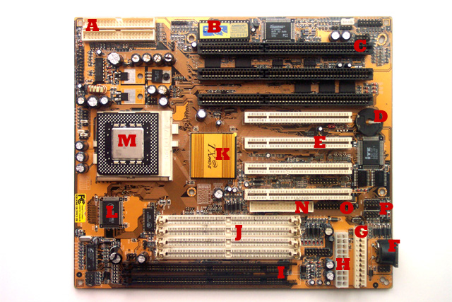 At Motherboard Diagram

 Pata Upgrading And Repairing Pcs The Ata Ide Interface Informit
Posting Komentar untuk "Ide Controller Diagram"